Submitted by florin on
| Attachment | Size |
|---|---|
| 639.03 KB | |
| 3.71 KB | |
| 68.79 KB | |
| 173.8 KB | |
| 4.58 KB | |
| 188.73 KB | |
| 177.95 KB | |
| 210.09 KB | |
| 304.03 KB | |
| 224.62 KB | |
| 28.47 KB |
When making a telescope mirror on the machine, two parameters are important: the rotation speed of the mirror, and the rotation speed of the overarm eccentric. Other environmental parameters also matter: temperature and humidity are foremost here. To more easily monitor and display these variables, I've built an electronic device that collects this data and shows it on the control panel. This is how to build the device.
First off, this is how the final result looks like:
Tachometer sensors
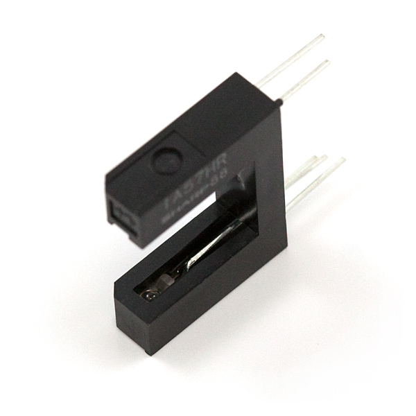
To measure rotation speed, the sensor could be a photo-interrupter - an infrared emitter and a receiver separated by a gap, like this:
https://www.sparkfun.com/products/9299

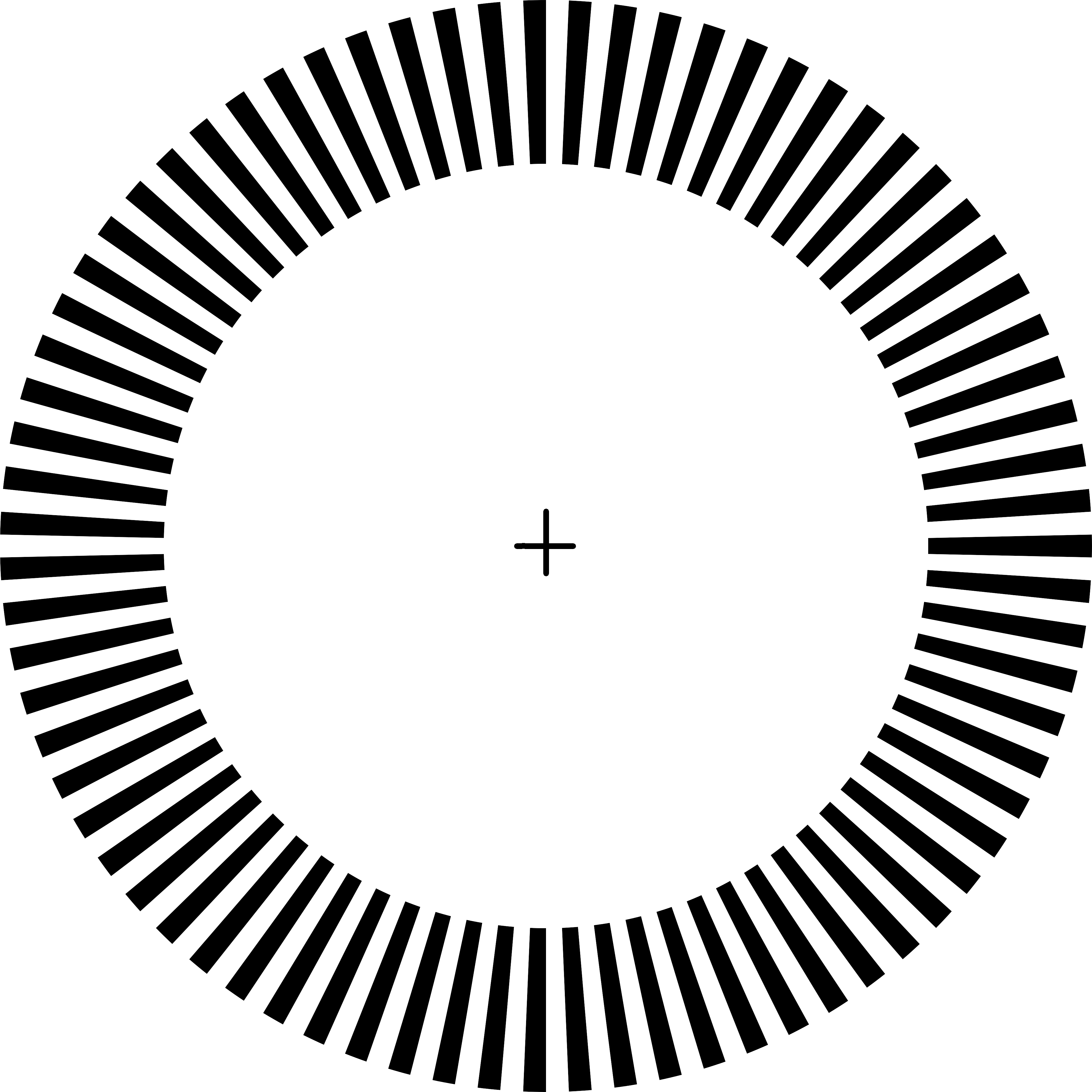
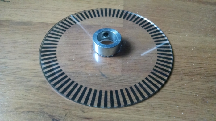
On the rotating element, install a transparent disk with a pattern on it that will interrupt the infrared beam as the disk is rotating:

Look at the end of this article for a file link called tachometer2.png, which contains the pattern already generated. Or you could generate a different pattern - here's a discussion on the GIMP forums on how to do it:
http://gimpforums.com/thread-how-to-draw-this-geometric-pattern-programm...
In case that discussion is deleted:
1. Install the dial-marks.py script (also linked at the end, rename it to .py if this website changes its extension) into ~/Library/Application\ Support/GIMP/2.8/plug-ins/
That's the place on OS X where GIMP keeps this stuff. Other OSs might use different paths.
2. Start GIMP, create a blank image, as high resolution as possible. I used 4000 x 4000. Warning: a lot of trivial tasks like closing a file or Zoom In will be very slow at this resolution, so just wait if GIMP seems to do nothing.
3. Go to: Filters / Render / Paths / Dial marks
4. Settings:
center x = 2000; center y = 2000
inner radius = 1400; outer radius = 2000
total marks = 75
mark width (degrees) = 2.4
[That's 360 / (2 * number of marks)]
Sides = Round
It will render the path with all the marks.
5. Go to: Select / From path
Wait a bit if the image is large, it might be slow.
6. Go to Bucket Fill, select the right color, click inside a mark, wait to fill.
7. Go to: Image / Guides / New guide
8. Make it horizontal, and choose position = 2000 (middle of image)
9. Make another guide, this time vertical
10. Choose the pencil tool, make sure the size is right. Hold Shift and draw a line near the center. It will snap to the guide. Hold Shift and draw a line near the other guide. Again, it will snap to the guide. This is how you get cross-hairs in the center.
Print that file on a transparent, flexible sheet of plastic.
From a rigid sheet of transparent plastic, cut a round piece. Make a hole in the center for the rod to pass through. Glue the flexible pattern on the rigid disk. Glue a set collar in the center, which will be used to affix the disk with the pattern to the rotating rod.
If you're planning to monitor the speed of two rods, make two items as shown above.
Install each disk on its rod, and position the photo-interrupter so that the printed pattern is crossing the infrared beam, like this:

Build the controller
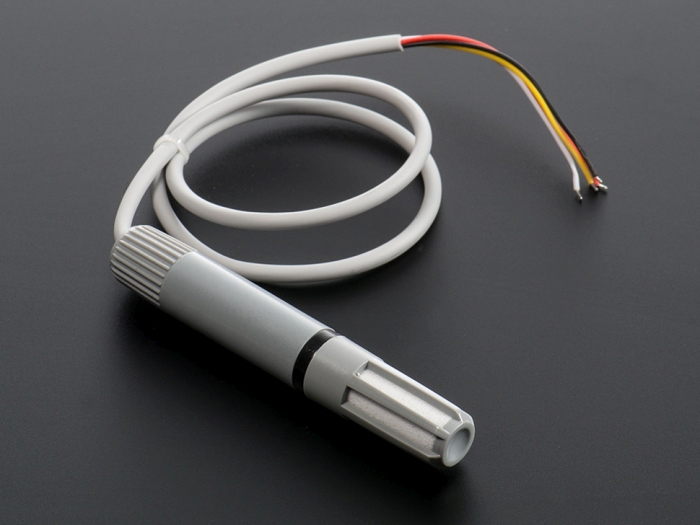
To measure the temperature and humidity, I've used an AM2315 sensor:
https://www.adafruit.com/products/1293

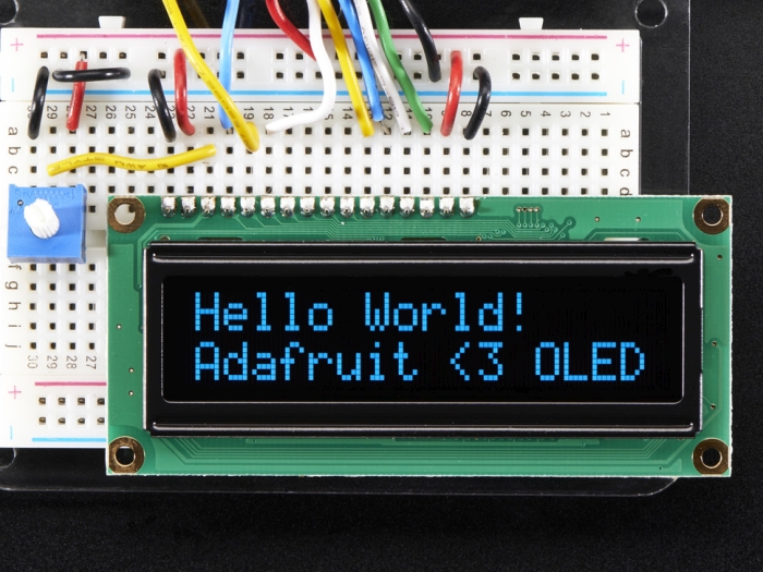
The display is a blue character 16x2 OLED:
https://www.adafruit.com/products/823

I've used an Arduino Mega 2560 to connect all sensors and the display, and to run the code. You could probably use a smaller Arduino for this project; I've chosen the Mega initially because it has lots of pins that allow you to experiment with peripherals, and then I just kept it as is, even though only a few pins are used for this project.
Check the mom_controller.ino file attached at the end for the Arduino code.
The code reads all sensors once every second (or once every 2 seconds for AM2315). The photo interrupters each increment a counter every time the infrared beam is blocked - these counters also are read once a second. After all readings take place, the display is updated, and the cycle repeats itself. The code uses the AM2315 and CharacterOLED libraries from Adafruit, and the PString library (link in the code).
The LED on the main Arduino board is used as a heartbeat indicator: it blinks on / off at every read / display cycle, therefore indicating that the controller is alive and doing its job. If the LED gets stuck, try to reset the controller.
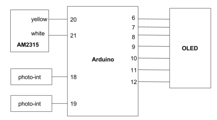
Connect everything
This is how everything is connected together:

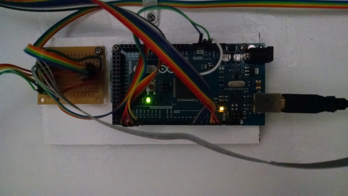
Use a small piece of perfboard to keep the connectors and any extra components, such as the resistors for the photo-interrupters:

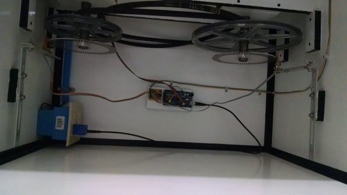
Place the controller in a safe place inside the machine, where it's out of the way and unlikely to get hit by the various moving parts. Give it +5V from a small USB charger. Connect it to all sensors.

The AM2315 temperature/humidity sensor should be placed outside, close to the mirror, but not so close as to get splashed with water or grit; somewhere on top of the overarm seems to be a good place. Run a long ribbon cable from it to the controller, and place a connector on the ribbon close to the sensor, so it's easy to disconnect if you're removing the overarm tower from the machine for cleanup.